|
5/23/2018 Manual Radiator Fan w/ an OEM SwitchIn preparation for my summer detail and service, I have decided to finally permanently install the radiator fan switch I wired last year. The switch manually triggers the high fans to help keep the car cool before it gets too hot, which is especially useful around town and in traffic. It is a simply modification, but it get can get complicated if like me you want to use OEM Porsche switches to trigger the fan. This is because Porsche used momentary switches that trigger action by relays, unlike a regular on/off switch that stays set to on or off, a momentary switch only sends a signal, it doesn't stay in the on or off position. Figuring out how to make this work sent me down several rabbit holes, and I have to thank Particlewave & Sandy who's posts helped me figure this out. The fan switch works by grounding pin 85 of the two high speed fan relays (#20 & #22). You can simply wrap the end of a wire around the relay pin, but I took fuse taps and filed the opening to fit the relay pins, then bent them with pliers to fit. I secured the wire to the relays with electrical tape before reinserting them in the relay panel. At this point you should have two wires one from Relay #20 and one from Relay #22. Since they will be triggered together, combine the wires into one before continuing. I used a butt connector to combine the two wires into a single wire. 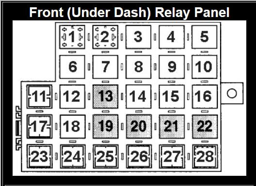 Now the way this works is by grounding the wire coming from the relay's pin 85. So next you need to identify the ground you want to use. I decided to use the ground from the phone connector under the center console because I already have several things wired to that location. However, we need to be able to interrupt this connection, which is where the switch comes in. You could stop here and use a regular on/off switch from an auto parts store, and be done with this hack for a few dollars. I have decided to use an OEM switch. I selected the rear defroster switch, it kind of looks like it makes sense for cooling something, and it has the correct internal circuitry (Type B switch) to operate for this purpose, including illuminating the amber LED in the switch when the fans are active, while still being able to be illuminated at night. However, to use an OEM switch you need a latching relay, which will work to convert the momentary switch input from the OEM switch to work like a regular on/off switch. To help explain how this all gets wired, I have modified a diagram created by Sandy on RennTech. 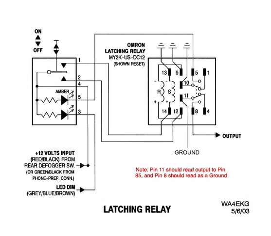 What is going here is pretty simple, but looks complicated.
Switch Pin 1 - Relay Pin 14 - Trigger Relay to Reset Position Switch Pin 2 - Relay Pin 12 - Trigger Relay to Set Position Switch Pin 5 - Relay Pin 5 - Trigger Amber Switch Light When Fans Are Active Switch Pin 3 - Illumination+ (from Cigarette Lighter or Other Dash Button) Switch Pin 4 - Switched 12V Power (from Phone Connector) Pins 1 & 2 on the switch represent the two sides of the rocker switch. When either side of the button is pressed either Pin 1 or Pin 2 is connected to Pin 4. This then triggers the latching relay to be in either the set or reset position (represented by the S and R in the diagram). That makes all of the switches in the relay toggle between the set or reset positions. This is basically the on/off function that is desired. The relay has two switches that are triggered when the relay changes between set and reset. These are represented by relays Pins 1, 5, 10 and Pins 4, 8, 11, and could be configured in different ways, but this is how I set it up. Pin 11 is connected to the wire coming from the fan relay pin 85. Pin 8 is connected to the phone connector ground. When the relay is triggered pin 85 will be grounded turning on the fans. On the other side, I have a wire going from pin 5 on the relay to pin 5 on the switch. This triggers the amber light inside the switch to turn on when the fans are activated. It also turns off when the fans turn off. Relay Pin 8 - Phone Connector Ground Relay Pin 11 - Pin 85 Fan Relay Wire Relay Pin 9, 10, 13 - Phone Connector Ground This project is still a work in progress, but I was excited to share the wiring for how this mod will work! I will post a complete DIY with better directions, diagrams, and part numbers once I finish installing this mod. Comments are closed.
|
Disclaimer
This website is a personal project, and any information contained on this website should be independently verified. I accept no liability and/or responsibility for the accuracy of any information on this website, and/or any damage you incur from reading or following any of the information on this website. This website contains documentation of my own modifications, upgrades, and other work, however your results may differ. I encourage everyone to do their own research and verify any information themselves. This website may be directly linked to without specific permission, but the contents may not be copied, hosted, transmitted, etc in any medium without express permission. Thank you! |
 RSS Feed
